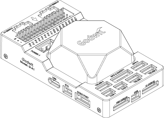
G-A1 | ArduPilot & PX4 Supported
The G-A1 is a state-of-the-art universal controller (flight controller) developed based on the Pixhawk Autopilot v6X Standard. It adopts a STM32H753 double-precision floating-point FMU processor, and a STM32F103 IO coprocessor. It also uses independent buses and power supplies. Multiple IMUs, each with its 6-axis inertial sensors, pressure/temperature sensors, and a geomagnetic sensor are designed for safety and rich expansion capabilities. With an integrated 10/100M Ethernet Physical Layer (PHY), the G-A1 can also communicate with the mission computer (airborne computer), high-end surveying and mapping cameras, and other UxV-mounted equipment for high-speed communications, meeting the needs of advanced UxV systems.
Product Information
Hardware Summary
| Item | Description |
|---|---|
| FMU Processor | STM32H753 (Arm® Cortex®-M7, 480MHz) |
| IO Processor | STM32F103 (Arm® Cortex®-M3, 72MHz) |
| Memory | 2 Mbytes of flash memory and 1 Mbyte RAM |
| Sensors |
|
| IO Interface |
|
| MicroSD Card | Not included in the package. |
| Power Requirement | 4.6V to 5.7V |
| Current Ratings |
|
| Operating Temperature | -40°C to +55 °C |
| Storage Temperature | -40°C to +70 °C |
| Operating Humidity | 5% to 95% (Non-condensing) |
| Casing Material | ABS (carrier board), Diecast Aluminum Alloy (IMU cover) |
| Dimensions | 92.2 (L) x 51.2 (W) x 28.3 (H) mm |
| Weight | 77.6g (carrier board with IMU) |
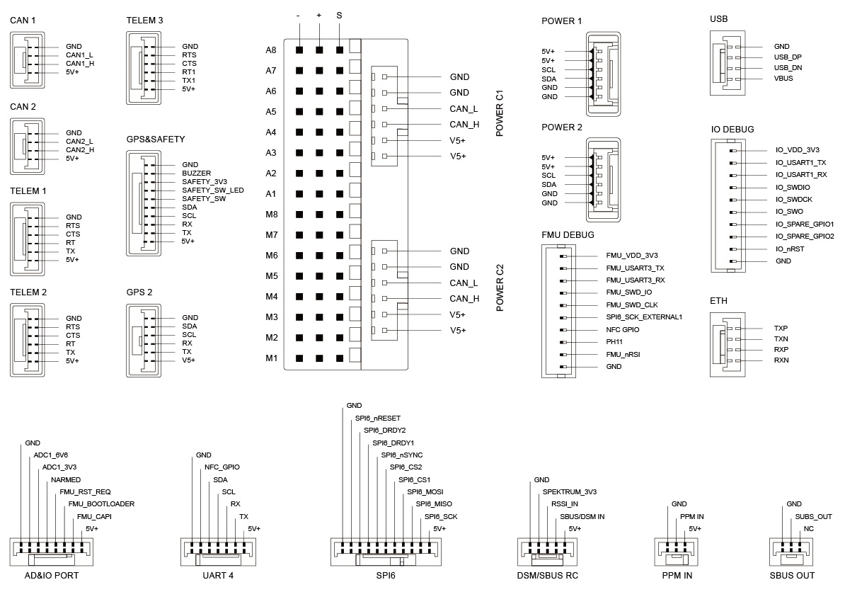
Pin Definition
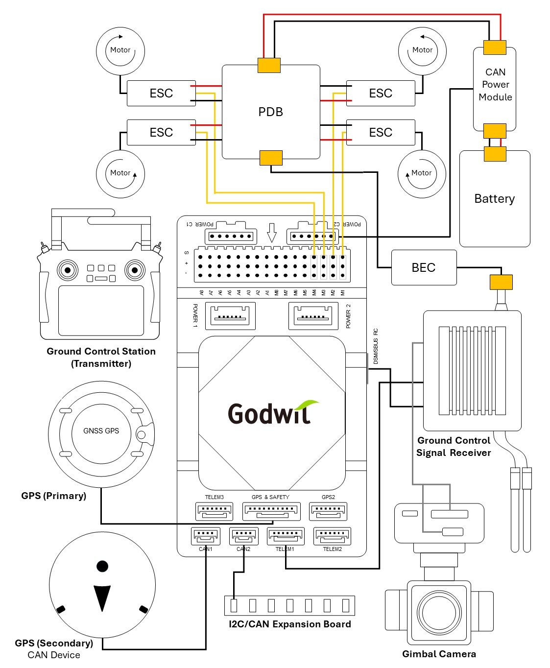
Wiring Overview
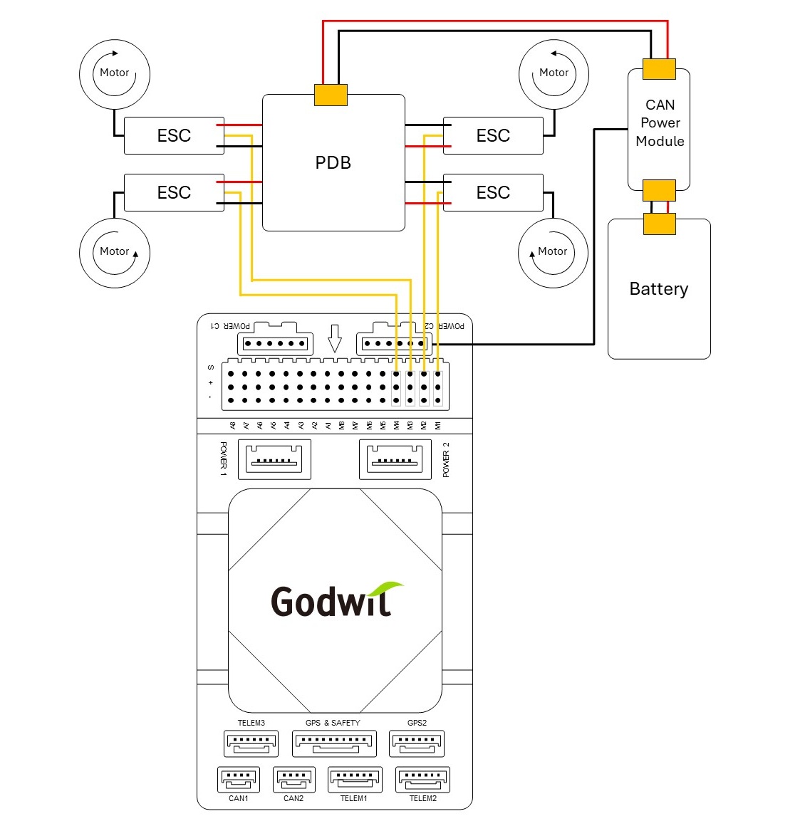
The diagram below shows G-A1 and the connections to its peripherals.
| Interface | Function |
|---|---|
| POWER C1 | Connect CAN PMU to POWER C1. Used with UAVCAN power modules. |
| POWER C2 | Connect CAN PMU to POWER C2. Used with UAVCAN power modules. |
| POWER 1 | Connect to an SMbus (I2C) power module. |
| POWER 2 | Connect to an SMbus (I2C) power module. |
| GPS&SAFETY | Connect to a GPS module, which includes GPS, safety switch, and buzzer interface. |
| GPS2 | Connect to a GPS/RTK module. |
| UART 4 | Enable user customization. |
| TELEM1/TELEM2/TELEM3 | Connect to telemetry or MAVLink devices. |
| MicroSD CARD | Insert a MicroSD card for log storage. |
| A1-A8 | Define as PWM/GPIO. Supports Bdshot, and can be used to connect camera shutter/hot shoe, servo, etc. |
| M1-M8 | PWM output from IO. Connect to ESCs and Servos. |
| USB | Connect to a computer for communication with the universal controller, such as firmware loading. |
| CAN1/CAN2 | Connect to Dronecan/UAVCAN devices. |
| DSM/SBUS/RSSI | Signal input interface for DSM, SBUS, or RSSI. Connect to a DSM satellite receiver, SBUS receiver, or RSSI signal module. |
| PPM | Connect to a PPM RC receiver. |
| ETH | Connect to Ethernet devices. |
| AD&IO | Connect to an analog input (ADC3.3 or ADC6.6). Usually not used. |
| FMU Debug | For use by professionals and developers. |
| IO Debug | For use by professionals and developers. |
Serial Port Mapping
| UART | Device | Port |
|---|---|---|
| USART1 | /dev/ttyS0 | GPS |
| USART2 | /dev/ttyS1 | TELEM3 |
| USART3 | /dev/ttyS2 | Debug Console |
| UART4 | /dev/ttyS3 | UART4 |
| UART5 | /dev/ttyS4 | TELEM2 |
| USART6 | /dev/ttyS5 | PX4IO/RC |
| UART7 | /dev/ttyS6 | TELEM1 |
| UART8 | /dev/ttyS7 | GPS2 |
Power Consumption
Voltage
| Parameter | Min | Typical | Max |
|---|---|---|---|
| 4.6V | 5V | 5.4V |
Current
| Parameter | Typical | Max |
|---|---|---|
| G-A1 + Components | 3.0Amp | 3.44Amp |
| G-A1 Only | 0.44Amp | 0.58Amp |
Quick Start
This quick start shows how to power the universal controller and connect its peripherals. Please refer to the image below to connect sensors and peripherals.
For other operation descriptions, please refer to the links below.
Vehicle Front
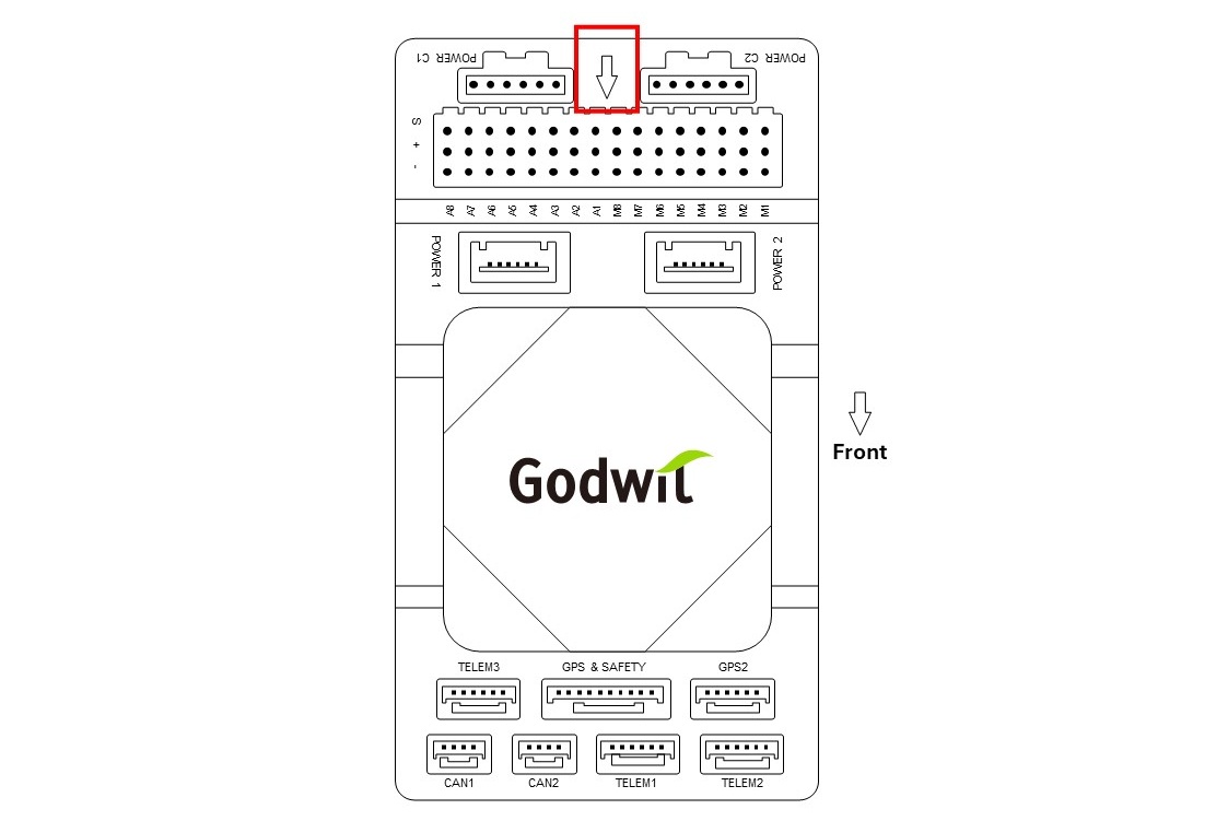
Notes:
If the controller cannot be mounted in the recommended/default orientation (e.g. due to space constraints), you will need to configure the autopilot software with the orientation that you actually used.
Firmware Support
G-A1 is supported by both Ardupilot and PX4 autopilot. Please visit the links below.
- Ardupilot Source Code
- Ardupilot Stable Release Ver. 4.6.3 Image File
- PX4 Source Code
This product includes open source software, please read the OPEN SOURCE SOFTWARE NOTICE.
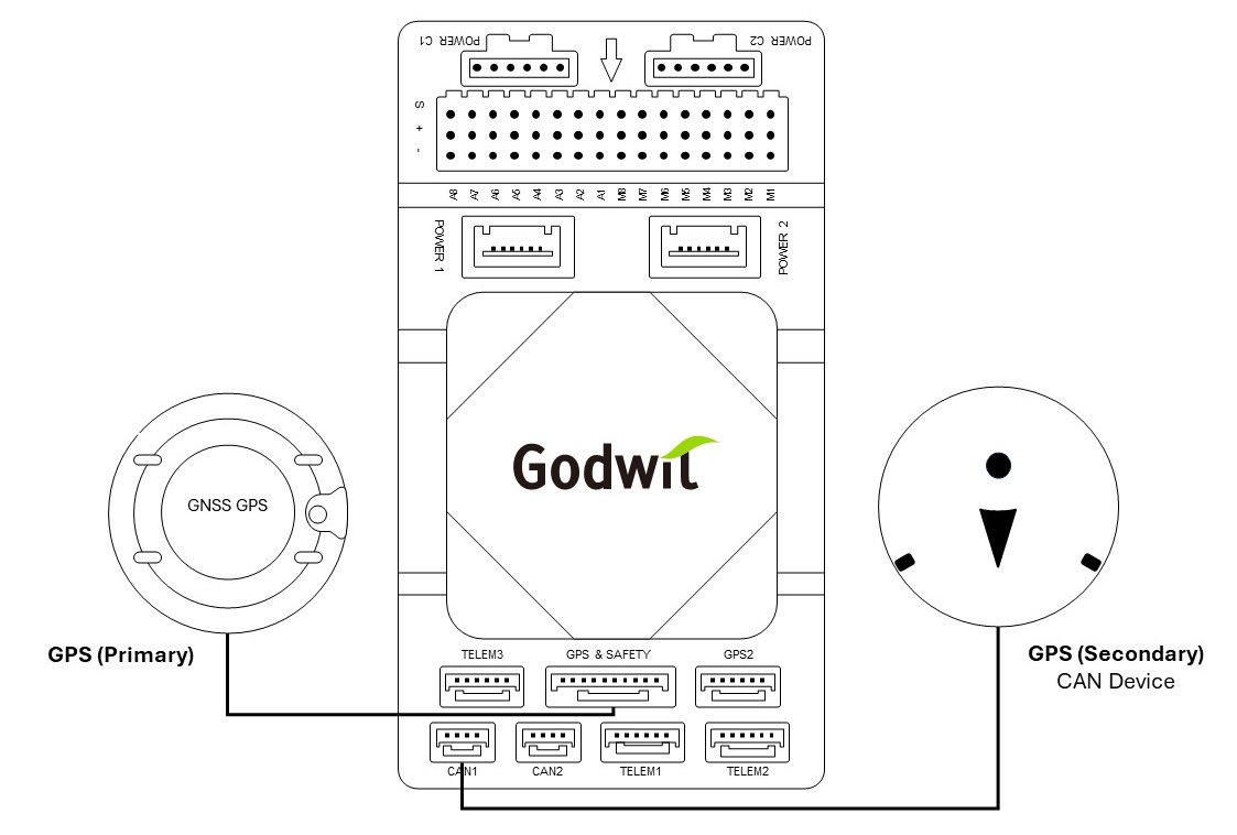
GPS
Connect the GPS/RTK module to the GPS & SAFETY interface.
The GPS module generally integrates a GPS receiver, compass, safety switch, buzzer, and an LED status indicator. When installing the module, it should be mounted on the frame as far away from other electronic devices as possible, with the direction marker pointing toward the front of the carrier board.
A CAN/UAVCAN GPS/RTK module can also be connected to the CAN1 interface as a secondary GPS.
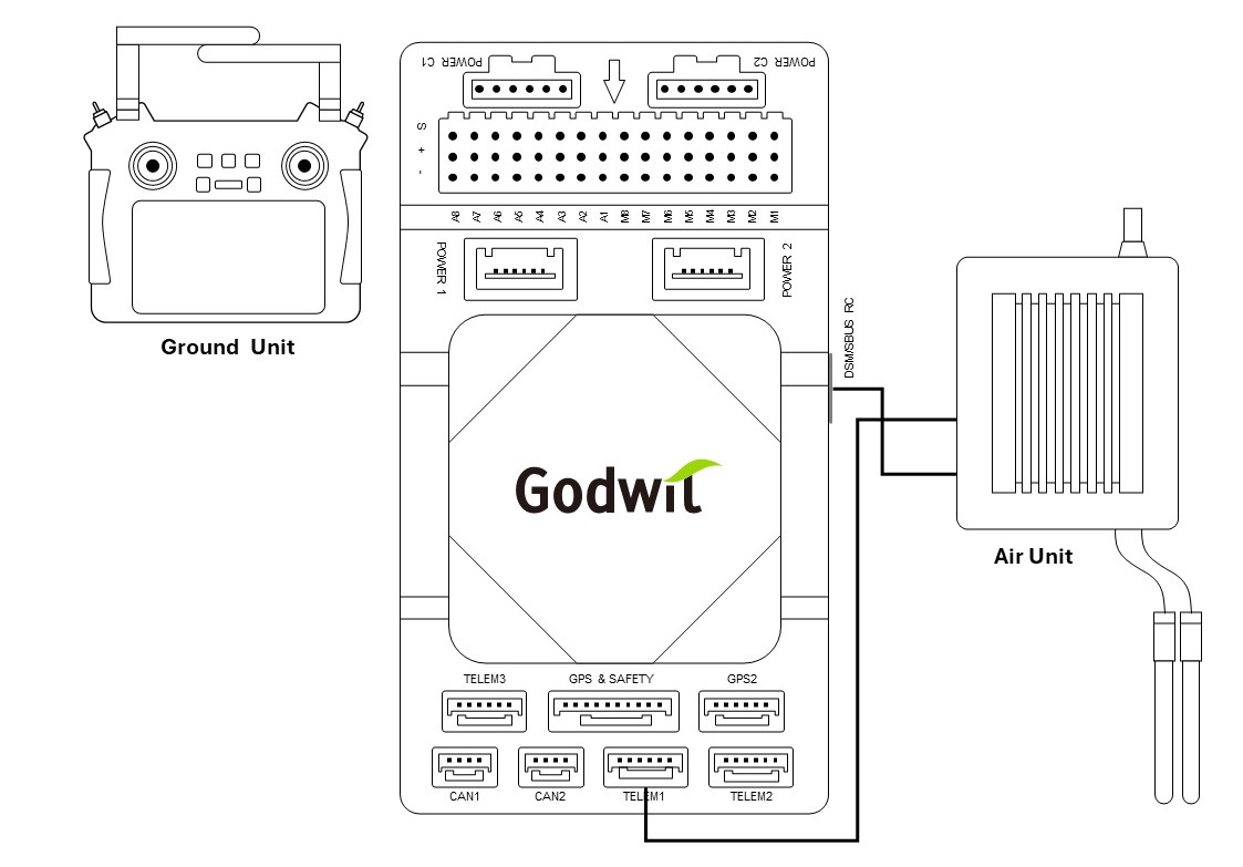
Telemetry (Radio) System
Using the telemetry system you can communicate with the vehicle through the ground station software. Monitor and control drones in flight. The air unit of the telemetry system should be connected to the TELEM1/TELEM2/TELEM3 interface.
For DSM/SBUS receivers, connect them to the DSM/SBUS interface, while PPM receivers should be connected to the PPM interface.
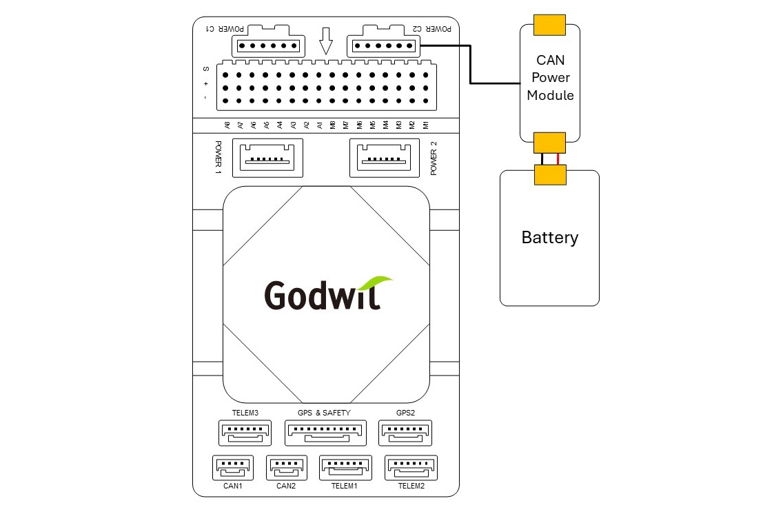
Power
This universal controller features a CAN PMU module that supports 3 to 14s lithium batteries. The PMU is not included in the package. You need to provide a PMU that complies with the specifications of the CAN PMU module. To ensure proper connection, attach the module’s 6-pin connector to the flight control Power C1 or Power C2 interface.
When running Ardupilot, the universal controller operates as a plug-and-play device, requiring no further configuration. When running PX4, set it according to [Power Module Setup (PX4)].
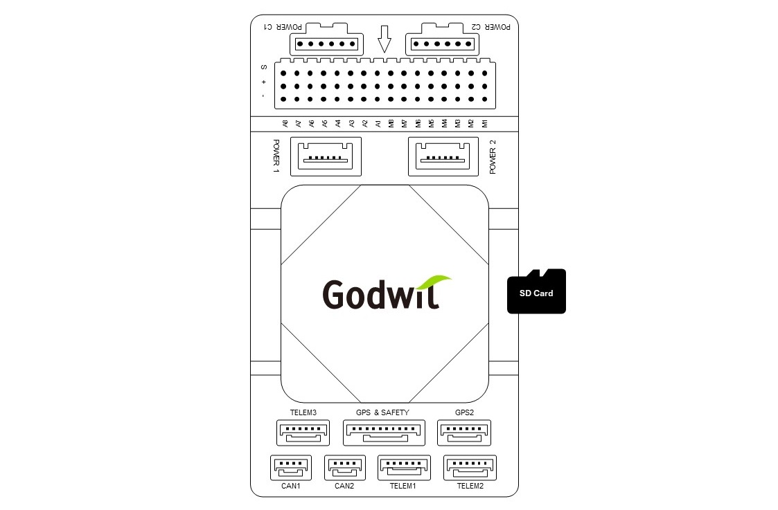
MicroSD Card
The MicroSD card is not included in the package. You need to prepare a MicroSD card and insert it into the socket.
A MicroSD card is highly recommended, as it is required to save logs and flight data.
Motor/Servo
Connect the motor and servo system to the M1–M8 and A1–A8 ports in the order indicated on the carrier board.
Servo Power Supply
This universal controller does not provide power to the servos. To power them, an external BEC must be connected to the positive and negative terminals of any A1–A8 or M1–M8 port.
Useful Links
Please refer to the links below for more useful information when assembling or operating the G-A1.
Ardupilot
- Information for the First Flight First Time Setup
- Godwit G-A1 Accton Godwit G-A1 on Ardupilot
PX4
- Introduction for Novic Users Using PX4 Basic Concepts
- Assembling a UAS Assembling a Multicopter
- Godwit G-A1 Accton Godwit G-A1 on PX4
- Pixhawk Standard Pixhawk Standard Autopilots|PX4 Gu