General
Which ground control station systems does the G-A1 support?
G-A1 is compatible with Ardupilot's Mission Planner and PX4's QGroundControl. Please choose the system you prefer to operate G-A1.
Does G-A1 support analog power modules?
Yes. Please use our Power (Type 2) Analog Cable to connect the analog power module to G-A1.
Power
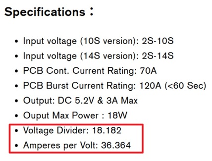
How can I determine the “Voltage Divider” and “Amperes per Volt” parameters?
Refer to the module’s specifications, manual, or datasheet provided by the manufacturer. For example, the configuration values for Holybro's PM06v2 module are listed in its specifications.
What should I do if the voltage or current value readings are incorrect?
You can calibrate (calculate) the Voltage Divider and Amperes per Volt for each system. Refer to the links below to configure the parameters for your system.
How many PMUs can I monitor at a time?
Provided that you have sufficient physical ports or use an expansion board from the accessory kit, the maximum number of PMUs supported across different connection types (Analog, I2C, and CAN) depends on the firmware.
ArduPilot allows monitoring of up to 9 PMUs simultaneously, whereas PX4 is limited to 2 PMUs.
Note that a maximum of 4 PMUs can be used for power delivery and redundancy, connected via the G-A1's POWER 1/2 and POWER C1/C2 ports. Any additional PMUs can be used only for data monitoring.
Should I select an I2C address when using an I2C power module?
Optional. Manual selection is typically unnecessary, as both ArduPilot and PX4 support automatic I2C address detection. You only need to configure the address manually if there is an address conflict with another device on the same I2C bus.
Note that manual I2C address override is available only in ArduPilot. To configure it, go to CONFIG > Full Parameter List and set BATT_I2C_ADDR to the value according to your PMU's specifications(e.g., Holybro's PM02D uses address 65).
Can I connect more than two CAN power monitors to the G-A1?
Yes, but with specific limitations. The details are explained below.
- Use POWERCx port: The setup process is identical to the steps mentioned in Digital Power Module Setup – DroneCAN Type chapter. Connect the other unit to the PowerC2 port using an additional PowerC Cable (included in the accessory kit).
- Use CANx port: This setup is recommended only when the G-A1 is already powered by a separate power source and no PowerC ports are available on the device. In this configuration, this CAN power monitor cannot power the G-A1. Ensure that your power monitor supports the DroneCAN protocol, then follow the steps below to configure it.
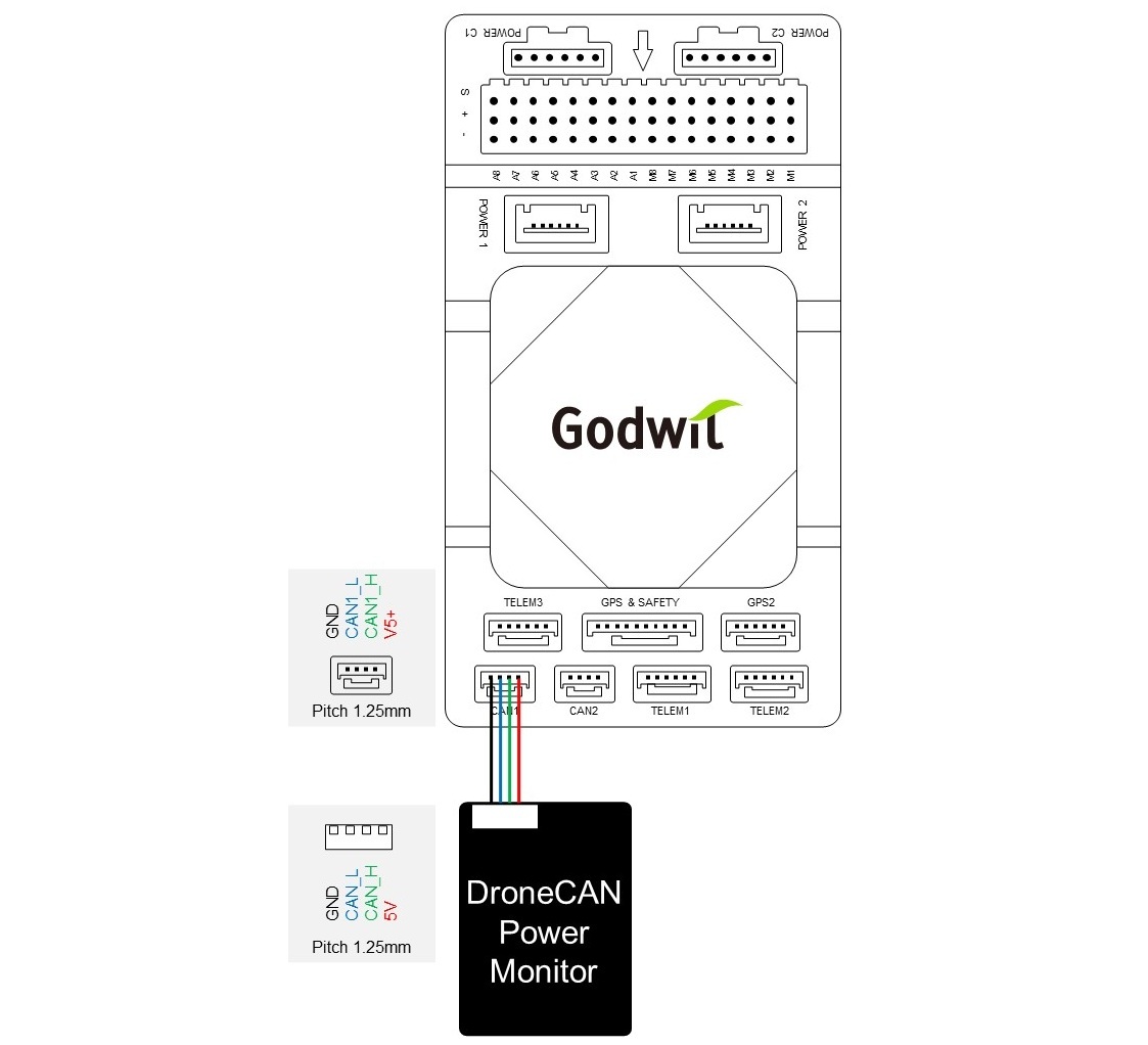
- Single CAN power monitor: Refer to the pinout diagram below to splice and solder the wires between the G-A1’s CAN port and the CAN power monitor. Please refer to Advanced Setup for software configuration.
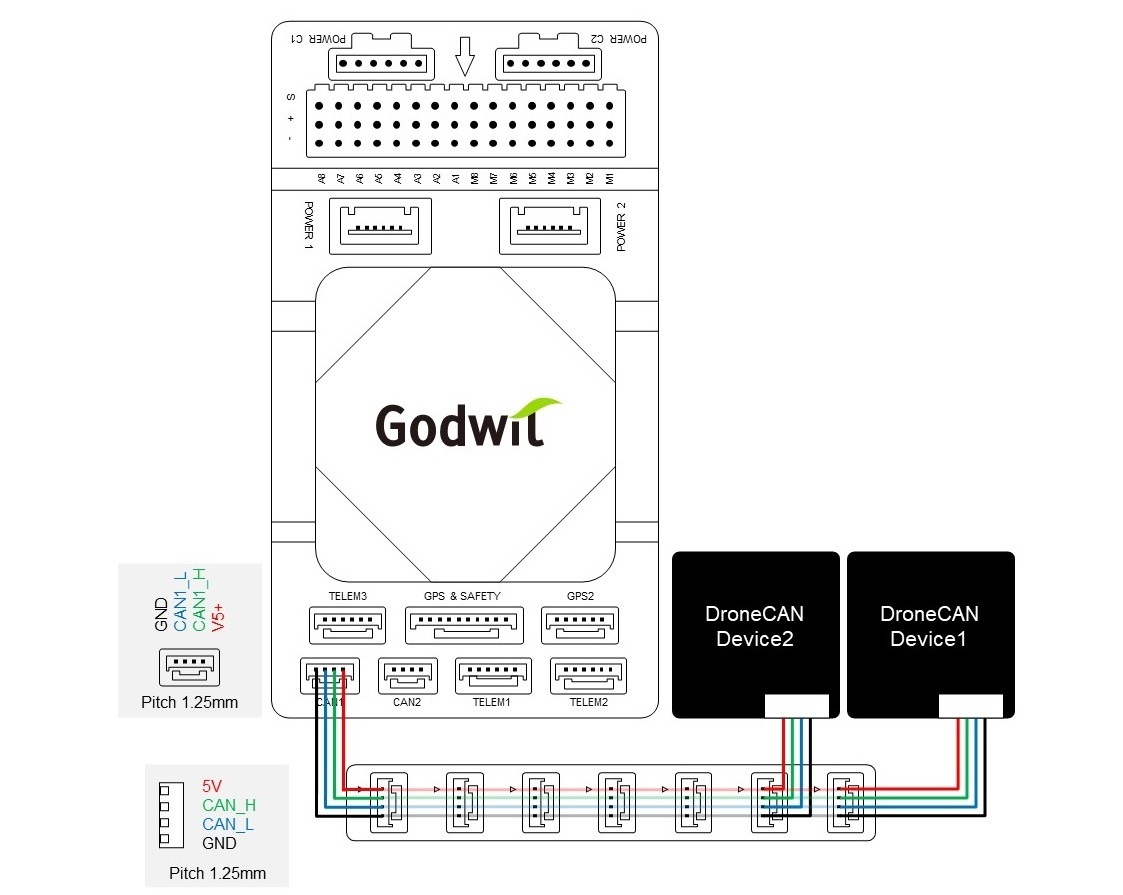
- Multiple DroneCAN monitors: Refer to the pinout diagram below, an Expansion Board (available in the accessory kit) can be used, to bridge the wires between the G-A1’s CAN port and the CAN power monitor. No additional configuration is necessary, as the software settings are identical for all connected devices.
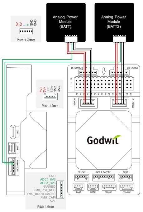
Can I connect two analog power modules to the G-A1 at the same time?
Yes. The G-A1 supports a maximum of two ADC inputs, allowing you to connect up to two analog power modules (one module per ADC input) and read the voltage from each module. In this configuration, current(I) is not measured.
Please refer to the wiring diagram shown below.
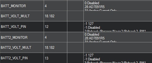
Configure the parameters according to your system. Below are an examples of the Holybro's PM0x parameter configuration.
Ardupilot - Mission Planner Configuration
- BATT_MONITOR: 4
- BATT2_MONITOR: 4
Ensure these ADC inputs are not used by any other parameters, and reboot or replug the G-A1 after completing the configuration.
- BATT_VOLT_PIN: 12 (corresponds to the ADC1_6V6 pin on the AD&IO port of G-A1)
- BATT_VOLT_MULT: 18.182
- BATT2_VOLT_PIN: 13 (corresponds to the ADC1_3V3 pin on the AD&IO port of G-A1)
- BATT2_VOLT_MULT: 18.182
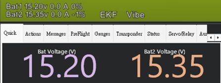
Go to Data > Quick page to check the batteries' voltage.
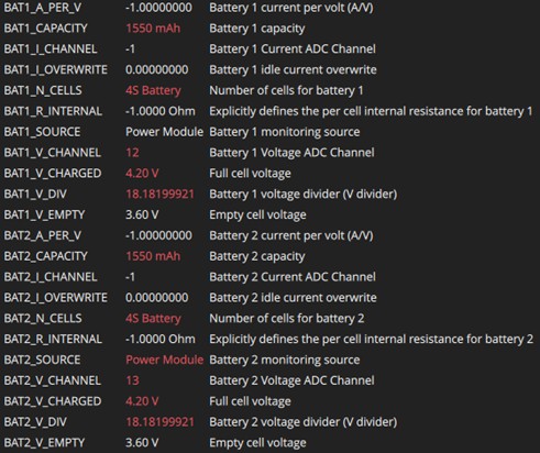
If required, configure BATx_CAPACITY and BATx_V_CHARGED to match the specifications of your battery.
- BAT1_SOURCE: Power Module
- BAT1_V_CHANNEL: 12 (corresponds to the ADC1_6V6 pin on the AD&IO port of G-A1)
- BAT1_V_DIV: 18.182
- BAT2_SOURCE: Power Module (You may need to reboot the G-A1 for the change to take effect.)
- BAT2_V_CHANNEL: 13 (corresponds to the ADC1_3V3 pin on the AD&IO port of G-A1)
- BAT2_V_DIV: 18.182
After completing the parameter configuration, reboot the G-A1, then verify that two battery icons are shown on the home page’s top bar.

Firmware
I want to upgrade my G-A1's firmware, but I cannot find its hardware ID in PX4’s QGroundControl.
Although the PX4 firmware already supports G-A1, QGroundControl’s internal hardware ID list has not yet been updated. PX4 will officially release support for G-A1 starting from version V1.17.
Can I upgrade G-A1’s firmware using PX4’s QGroundControl?
No. Since the G-A1 is not yet listed in QGroundControl hardware ID list, please use ST-Link or Mission Planner to upload the firmware instead.
How can I upgrade G-A1’s firmware via ArduPilot’s Mission Planner?
Please refer to Advanced Setup for the upgrade process.
Drone Configurations
How do I configure the G-A1 for a Tailsitter VTOL drone?
The configuration of a tailsitter is different from that of a multirotor UAV. Please refer to the steps below to complete the installation and configuration of your drone.
QTailsit Configuration
- Download and install the G-A1's arduplane firmware from the ArduPilot website.
- Open Mission Planner on your laptop.
- Connect the G-A1 to Mission Planner via a USB Type-C cable.
- After Mission Planner receives data, open Config > Full Parameter List.
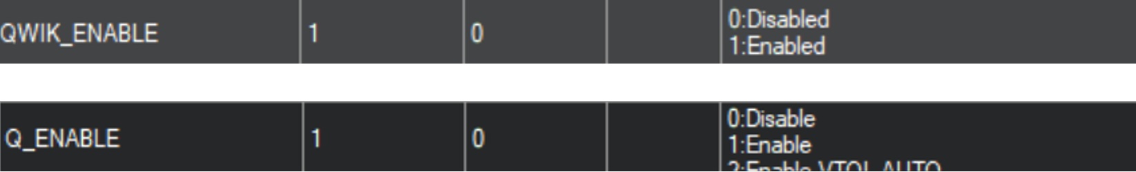
- Set the values as following, then reboot the G-A1 for the change to take effect.
- QWIK_ENABLE: 1
- Q_ENABLE: 1
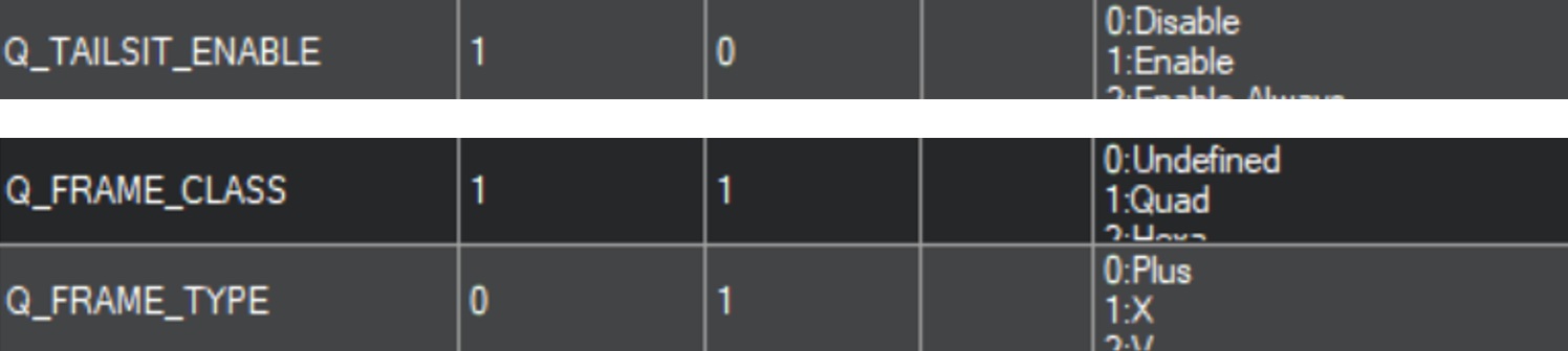
- Set the values as following, then reboot the G-A1 for the change to take effect.
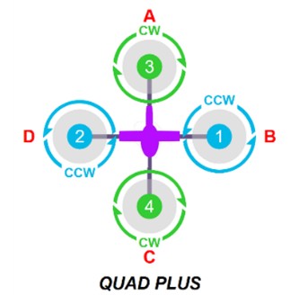
- Q_FRAME_CLASS: 1 (Qard)
- Q_FRAME_TYPE: 0 (Plus)
- Q_TAILSIT_ENABLE: 1
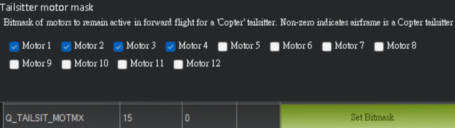
- Check the Motor 1-Motor 4 boxes in Q_TAILSIT_MOTMX.
- Set BRD_SAFETY_DEFLT to 0 to disable the default state of the SAFETY SWITCH, then reboot the G-A1 for the change to take effect.

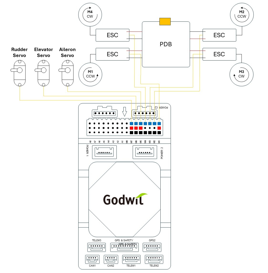
Hardware Connection
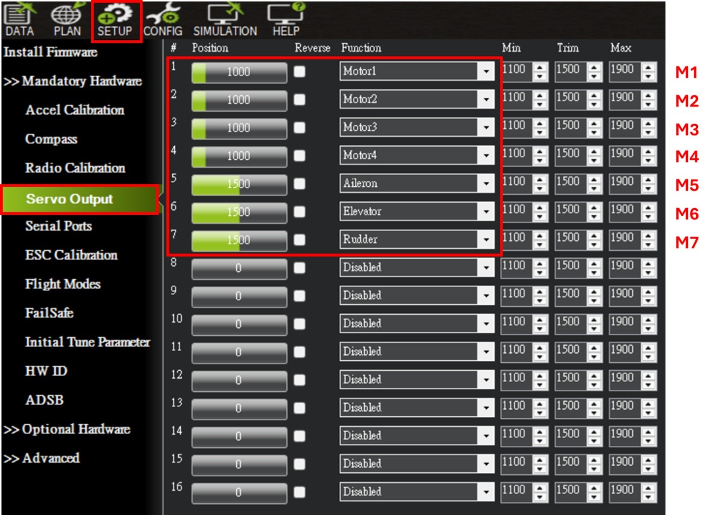
Connect M1-M4 to motor's ESC and M5-M7 to servos according to the colored blocks shown in the diagram below. Note that all connected ESCs only require one power wire to be connected to supply power to the servos.
Servo Output Configuration
Set the values of M1-M8 as following. No throttle setting is required, as the airframe does not have dedicated motors for forward (horizontal) flight.
Adjust whether reversal is needed based on your romote controller (transmitter) requirements.
Motor Test
Use the buttons highlighted in the red to individually test Motor 1–4 (corresponding outputs in Servo Output). It is recommended to set the Throttle to 10% and Duration to 5 seconds.
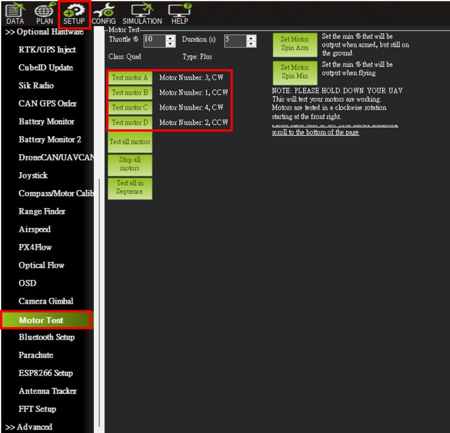
Test each motor individually, and follow the motor layout shown below to verify that the rotation direction at each position is correct (as indicated next to each button).